
Smartscan Saftey Light Curtain MFU-M1: Muting Module - Single Light Curtain
Status Indicators
Inputs - Green LED ON when input is ON
Outputs - Green LED ON when input is ON
Reset - Yellow LED ON when reset input in ON
EDM - Yellow LED ON when EDM inputs are ACTIVE
Status - RED LED's ON steady when system is OK
RED LED's FLASH ON/OFF when system is in lockout condition
Wiring Information
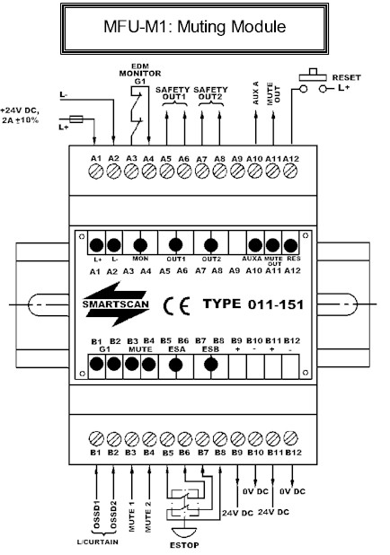
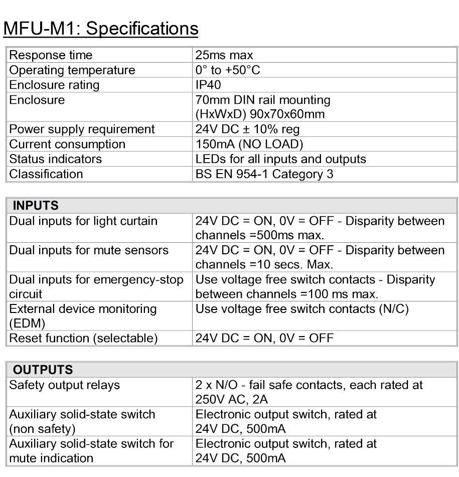
Terminals A1 and A2 – Power supply input - Connect a suitably stabilized 24V DC power supply
to terminals A1 = +24V DC and A2 = 0V DC. The current consumption of the MFU with no load
applied on the output switching terminals is 150mA.
Terminals A3 and A4 – External device monitor (EDM) - Normally closed switch contacts, in series from the external power switching devices are connected across terminals A3 and A4. The monitoring circuit checks that the power switching devices both de-energize at the same time the MFU safety output switches de-energize. If one or both of the power switching devices fail to de-energize at this time the MFU goes into a lockout condition, turning all output switches off.
To reset from as lockout condition it is necessary to remove the 24V DC supply from the MFU and then re-apply.
If the EDM circuit is not used it is necessary to link terminals A3 & A4 otherwise the system will go into a lockout condition at eh next demand upon the safety system.
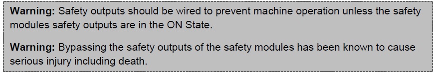
Terminals A5 and A6 – Safety output 1 switch contact - Connect terminals A5 and A6 to one channel of a machine’s stop circuitry. For example, via an external power-switching relay or directly to a safe PLC input or a machines final control element.
Terminals A7 and A8 – Safety output 2 switch contact - Connect terminals A7 and A8 to one channel of a machine’s stop circuitry. For example, via an external power-switching relay or directly to a safe PLC input or a machines final control element.
If a single channel safety circuit is used link terminals A6 & A7. Terminals A5 & A8 are then connected to the machine's safety circuit. Connecting in this way links safety output switch 1 and safety output switch 2 in a series configuration.
Inputs - Green LED ON when input is ON
Outputs - Green LED ON when input is ON
Reset - Yellow LED ON when reset input in ON
EDM - Yellow LED ON when EDM inputs are ACTIVE
Status - RED LED's ON steady when system is OK
RED LED's FLASH ON/OFF when system is in lockout condition
Wiring Information
Terminals A1 and A2 – Power supply input - Connect a suitably stabilized 24V DC power supply
to terminals A1 = +24V DC and A2 = 0V DC. The current consumption of the MFU with no load
applied on the output switching terminals is 150mA.
Terminals A3 and A4 – External device monitor (EDM) - Normally closed switch contacts, in series from the external power switching devices are connected across terminals A3 and A4. The monitoring circuit checks that the power switching devices both de-energize at the same time the MFU safety output switches de-energize. If one or both of the power switching devices fail to de-energize at this time the MFU goes into a lockout condition, turning all output switches off.
To reset from as lockout condition it is necessary to remove the 24V DC supply from the MFU and then re-apply.
If the EDM circuit is not used it is necessary to link terminals A3 & A4 otherwise the system will go into a lockout condition at eh next demand upon the safety system.
Terminals A5 and A6 – Safety output 1 switch contact - Connect terminals A5 and A6 to one channel of a machine’s stop circuitry. For example, via an external power-switching relay or directly to a safe PLC input or a machines final control element.
Terminals A7 and A8 – Safety output 2 switch contact - Connect terminals A7 and A8 to one channel of a machine’s stop circuitry. For example, via an external power-switching relay or directly to a safe PLC input or a machines final control element.
If a single channel safety circuit is used link terminals A6 & A7. Terminals A5 & A8 are then connected to the machine's safety circuit. Connecting in this way links safety output switch 1 and safety output switch 2 in a series configuration.
Terminal A9- No Connection
Terminal A10 – Auxiliary electronic switching output 1 - The Auxiliary switching output should only be used for non-safety critical application. For example connecting an indicator lamp or as feedback to a PLC to confirm the safety outputs have de-energies.
The auxiliary output energizes when safety output switches 1 and 2 energize and de-energizes when the safety outputs de-energize. Auxiliary output ON = 24V DC and OFF- 0V DC.
Terminal A11 – Auxiliary electronic switch – mute out.- The Auxiliary switching circuit energizes when the light curtain is muted, e.g. when suitable signals have been applied to terminals B2 and B3. The output switch is normally used for connecting an indicator lamp or as feedback to a PLC to confirm safety light curtain inputs at terminals B1 and B2 are overridden e.g. in a muted condition.
Terminal A12 – Reset - A suitable switch should be connected between terminal A12 and the 24V
DC supply. If the safety output relays de-energize a depression of the switch is required to
re-energize the output switches to an ON condition.
The MFU's safety output switches will only re-energize when the reset switch is depressed and the released.
Terminal B1 and B2 – light curtain inputs (OSSD1 and OSSD2) - Connect the electronic output switches (OSSD1 and OSSD2) of a light curtain to terminals B1 and B2 respectively.

Terminal B3 and B4 – mute input signals - Connect suitable mute initiating signals to terminals B3 and B4 respectively. The mute signals override the light curtains operation therefore, the inputs should only be active during safe periods of the machinery’s operating cycle.
Terminals B5/B6 and B7/B8 – dual channel emergency stop circuit - Connect one channel of the machines emergency stop circuit between terminals B5 and B6 and the second channel between terminals B7 and B8.
An internal circuit monitors for short circuits and switching disparity between the two input channels. If the inputs do not switch together (within 100ms of each other) the system will go into a lockout condition. This configuration meets the the requirements for 'control reliability' and cannot be used in a single channel configuration.
An internal circuit monitors for short circuits and switching disparity between the two input channels. If the inputs do not switch together (within 100ms of each other) the system will go into a lockout condition. This configuration meets the the requirements for 'control reliability' and cannot be used in a single channel configuration.

Terminals B9 and B11 – 24V DC supply - Additional + 24V DC outputs for connecting to the light curtains etc.
Terminals B10 and B12 – 0V DC supply - Additional 0V DC outputs for connecting to the light curtains etc
Terminals B10 and B12 – 0V DC supply - Additional 0V DC outputs for connecting to the light curtains etc