
Smartscan Safety Light Curtain SG: Controls Information (physical wiring)
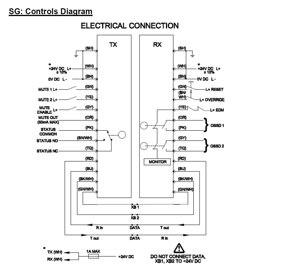
Power supply - Use a regulated supply +24V DC ±10%. Protect the +24V input with a 1 A fuse. Connect the power supply to both the transmitter (TX) and receiver (RX) cables as follows: Connect conductors of both the transmitter and receiver to WHITE wire to +24V DC and the BROWN wire to 0V DC.

EDM (External Device Monitoring) - This input is used to monitor external switching devices to ensure those devices respond each and every time the light curtain is interrupted. There is and LED indicator located in the receiver (RX) column that illuminates when the EDM circuit is complete.
When monitoring a switching device one side of the Normally Closed circuit will connect to the YELLOW wire of the receiver (RX) cable the other side to +24V DC. If the EDM function is not required +24Vdc must be connected to the YELLOW wire otherwise the system will remain tripped and will not reset.
When monitoring a switching device one side of the Normally Closed circuit will connect to the YELLOW wire of the receiver (RX) cable the other side to +24V DC. If the EDM function is not required +24Vdc must be connected to the YELLOW wire otherwise the system will remain tripped and will not reset.

Reset - A push button or key switch is required. To give the system a manual restart signal apply +24Vdc to GREEN wire of the receiver (RX) cable, releasing the switch will restart the safety outputs to an ON condition, providing the light curtain is clear of obstruction and the operator has checked to ensure that the dangerous area is safe. If using a PLC to pulse the reset signal the pulse width should be 100 ms or more.
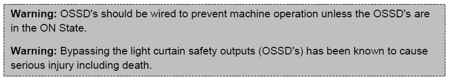
Safety Outputs (OSSD’s) : These safety outputs respond to interruption of the light curtain (unless muted or blanked). The relays close (ON) when the curtain is clear and open (OFF) when the curtain is blocked. They are cross-monitored voltage free contacts with a maximum contact switching power 24Vdc, 2A additionally there are status LED’s located in the top of the receiver column that illuminate when the safety outputs are in the ON or OFF state.
OSSD1 (Safety Output 1): Receiver (RX) cable – ORANGE wire & PINK Wire
OSSD2 (Safety Output 2): Receiver (RX) cable – GRAY wire & TURQUOISE Wire.
Status Output – The status output is a change over NON-SAFETY relay output. The status relay output consist of (1) common, (1) normally open position and (1) normally closed position. The status relay output is synchronous with the safety output. Additionally there is an LED located in the bottom of the transmitter (TX) column that illuminate when the status output is in the ON.
Status Output (Common): Transmitter (TX) cable – PINK wire.
Status Output (Normally Open): Transmitter (TX) cable – BROWN / WHITE wire
Status Output (Normally Closed): Transmitter (TX) cable – TURQUOISE Wire
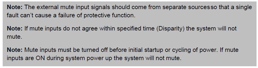
Mute Inputs (Mute1, Mute2) - Mute inputs (Mute 1, Mute 2) are mute inputs that should be applied to suitable external mute initiating devices. Both mute inputs (mute1 & mute 2) must switch within 2 seconds of each other or the light curtain will not mute (The time interval known as disparity, can be change via dipswitches in the Learned Mode of the light curtain ) When both inputs are active ON (receive 24Vdc), the light curtain will mute (*full mute or **partial mute), e.g. the guards’ safety outputs (OSSD’s) will not respond to an interruption of the light curtain. The light curtain will remain muted for a maximum time (15 minutes or infinite) that can be selected via dipswitch 3 in the standard mode. Additionally there are mute LED indicators located in the top of the transmitter (TX) column that illuminate when the mute signals are applied. Once either of the mute inputs is deactivated (turned OFF) the system will remain muted for an additional 2 seconds as a default.
*Full Mute: The entire sensing region of the light curtain will mute. (Default)
**Partial Mute: A window (specified number of beams) will mute; the remainder of the light curtain
is active. Selectable via dipswitches in the Learned mode.
Mute1: To apply mute 1 signal GREEN wire of the transmitter (TX) cable must receive a
+24Vdc signal.
Mute2: To apply mute 2 signal YELLOW wire of the transmitter (TX) cable must receive a
+24Vdc signal.
Status Output (Common): Transmitter (TX) cable – PINK wire.
Status Output (Normally Open): Transmitter (TX) cable – BROWN / WHITE wire
Status Output (Normally Closed): Transmitter (TX) cable – TURQUOISE Wire
Mute Inputs (Mute1, Mute2) - Mute inputs (Mute 1, Mute 2) are mute inputs that should be applied to suitable external mute initiating devices. Both mute inputs (mute1 & mute 2) must switch within 2 seconds of each other or the light curtain will not mute (The time interval known as disparity, can be change via dipswitches in the Learned Mode of the light curtain ) When both inputs are active ON (receive 24Vdc), the light curtain will mute (*full mute or **partial mute), e.g. the guards’ safety outputs (OSSD’s) will not respond to an interruption of the light curtain. The light curtain will remain muted for a maximum time (15 minutes or infinite) that can be selected via dipswitch 3 in the standard mode. Additionally there are mute LED indicators located in the top of the transmitter (TX) column that illuminate when the mute signals are applied. Once either of the mute inputs is deactivated (turned OFF) the system will remain muted for an additional 2 seconds as a default.
*Full Mute: The entire sensing region of the light curtain will mute. (Default)
**Partial Mute: A window (specified number of beams) will mute; the remainder of the light curtain
is active. Selectable via dipswitches in the Learned mode.
Mute1: To apply mute 1 signal GREEN wire of the transmitter (TX) cable must receive a
+24Vdc signal.
Mute2: To apply mute 2 signal YELLOW wire of the transmitter (TX) cable must receive a
+24Vdc signal.
Mute enable input: This signal must be applied for muting to occur. It may be used as a 3rd mute signal. When self-muting light curtains are used on conveyor systems” Conveyor Run” can start the muting sequence. This technique makes deliberate bypass of the light curtain more difficult. The mute enable signal has a status LED located in the bottom of transmitter (TX) column that illuminates when the mute enable signal is applied.
Mute Enable: To apply the mute enable signal, the GRAY wire of the transmitter (TX) cable must receive a +24Vdc signal.
Mute Output: Some machines require a mute signal to indicate that the light curtain is muted. The mute output is an electronic NON-SAFETY output that is ON =+24Vdc when the light curtain is muted and OFF = 0vdc when the light curtain is not muted. This electronic output is rated 24VDC@50mA and has a status LED located in the transmitter (TX) column that illuminates when the light curtain is muted.
To complete the mute output circuit conductor ORANGE of the transmitter (TX) cable must
be connected to 0Vdc.
Guard Override: Turning and holding the activate switch in the ON state will automatically turn-on the safe output relay switching contacts for a period of 3 minutes, providing the light curtain is in a tripped condition e.g. with the curtain blocked by a loaded pallet. As soon as the loaded pallet clears the light curtain the safety system will automatically reactivate to a ‘fully guarded’ condition. Now, release the activate switch and restart the safety system in the normal manner.
Guard Override: To apply the guard override signal, the BROWN / WHITE wire of the receiver (RX) cable through a normally open contact to +24VDC.
Cross Beam Communication Link: The cross beam communication conductors must be connected properly for the self-muting system to work, they relay information between the transmitter and receiver columns.
Connect the GREEN/ WHITE wire of the transmitter (TX) to the GREEN / WHITE wire of the
receiver (RX).
Connect the BLACK / WHITE wire of the transmitter (TX) to the BLACK / WHITE wire of the
receiver (RX).
Communication Link: The communication conductors must be connected properly for the system to work, they relay information between the transmitter and receiver columns.
Connect RED wire of the transmitter (TX) to RED wire of the receiver (RX)
Connect BLUE wire of the transmitter (TX) to BLUE wire of the receiver (RX).
