Smartscan Safety Light Curtain 1000 Series: Controls Information
Transmitter OK: A yellow ‘blinking’ indicators in the transmitter column indicates the unit is
powered-up and the electronic system operationa
powered-up and the electronic system operationa
Communication OK: A yellow ‘blinking’ indicators in the receiver column indicates that
communication is established between transmitter and receiver.
OSSD's ON: Green LED indicator at the receiver unit illuminates when the electronic output
switches, OSSD1 and OSSD2 are ‘ON’ (only when the light curtain detection zone is ‘clear’ of any obstruction).
OSSD's OFF: Red LED indicator in the RX unit illuminates when the electronic output switches,
OSSD1 and OSSD2 are ‘OFF’ e.g. a trip condition or, when the light curtain detection zone is
‘blocked’.
Lockout: Red LED indicator FLASHING( fault detected).
Output Fault: Green LED indicator FLASHING.
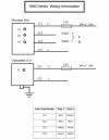
Output Signal Switching Devices(OSSD1,OSSD2): Outputs ‘ON’ = 24V DC, Outputs ‘OFF’ = 0V DC. Maximum switching current for each output = 24V DC, 500mA. Cable colors for output switches **CC3 = OSSD1, **CC4 = OSSD2.
Two independent electronic switches provide the fail-safe signals for switching a safe control relay
or electrical contactor. Both output signals are termed, ‘control reliable’; the transistor output switches are automatically turned ‘OFF’ for a very brief period of time to enable the electronicsafety system to automatically self check thus ensuring the switches are able to turn OFFpermanently if required to do so. This function increases the safety integrity of the Smartscan1000 system to a very high level. The switching period is so short (500 µs max.) that it has noeffect on the output signal to the machine safety circuits, thus the machine will continue to operate during the automatic test periods.
OSSD1 and OSSD2 - Each output switch has a maximum current rating of 0.5A.To prevent possible damage never exceed the maximum current rating for the switching devices.
Power Supply: A regulated power supply is required: +24V DC, up to 1.5A dependent on OSSD loads ±10%. Cable colors for power supply connections at both transmitter and receiver:
**CC1 = +24V DC,** CC2 = 0V DC.
A 24V DC regulated power supply should be used for connection to the transmitter and receiver
units. The transmitter and receiver units operate entirely independently from each other, e.g.
there are no electrical connections between the transmitter and receiver units therefore separate
24V DC power supplies may be used if required.
In order to protect the 1000 Series electronic system please remember to install fuses of suitable rating between incoming 24V DC supply and 24V input connections at both the transmitter and
receiver units. Recommended fuse ratings, transmitter 0.5A and receiver 1.5A.
Ensure both transmitter and receiver units are connected to GROUND. Insert an M6 bolt into one
of the threaded slots in the extrusion to ensure a good ground connection.
** See 1000 Controls Diagram**
Extending Cable of Transmitter and Receiver Columns: When extending the TX and RX cables
the following guidelines must be met.
- Use low capacitance shielded cable with a maximum effective capacitance of 2nF.
- Ground the shielded cable to reduce the possibility of EMI.
- Maximum overall cable length 50 meters.


