Smartscan Safety Light Curtain Pallet Safe Series: Controls Information
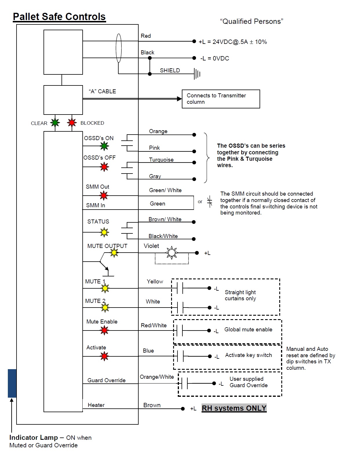
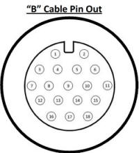
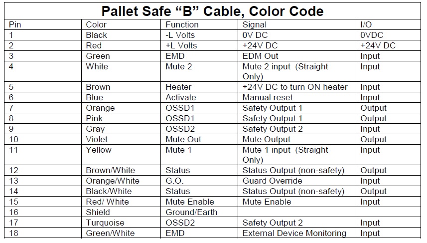
Power supply - Use a regulated supply +24V DC, 1A ±10%. Protect the +24V input with a .5A fuse. Connect the power supply to cable B as follows: The RED wire to +24V DC and BLACK wire to 0V DC. Connect the shield to ground.
EDM (External Device Monitoring) - This input is used to monitor external switching devices to ensure those devices respond each and every time the light curtain is interrupted. A red LED in the receiver column of the light curtain illuminates when the EDM circuit is complete.
The EDM circuit must receive continuity to function properly; no external voltage should be applied. When monitoring a switching device one side of the Normally Closed circuit will connect to wireGREEN/WHITE wire (cable B), the other to wire GREEN. If the EDM function is not required connect wire GREEN/WHITE directly to wire GREEN otherwise the system will remain tripped and will not reset.
|
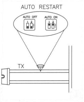
Reset Modes: Dipswitches located in the horizontal section of the transmitter column controls the reset modes. There are two reset modes automatic reset and manual reset.
Manual Start- A push button or key switch is recommended. Turning the ‘activate switch to ON and then releasing the switch will restart the safety outputs (OSSD’s) to an ON condition, providing the light curtain is clear of obstruction. If a PLC is used to manually reset the light curtain a minimum pulse width of 150 ms is required. Dipswitches in TX are in the OFF position. Activate: BLUE wire to 0V DC. Automatic Restart - No manual reset is needed; the light curtain restarts itself once the obstruction is cleared. The activate signal must be disconnected in this mode.. Dipswitches in TX are in the ON position. |
|

Guard Override: Turning and holding the guard override switch in the ON state will automatically turn-on the safe output relay switching contacts for a period of 3 minutes, providing the light curtain is in a tripped condition e.g. with the curtain blocked by a loaded pallet. As soon as the loaded pallet clears the light curtain the safety system will automatically reactivate to a ‘fully guarded’ condition. Now, release the guard override switch and restart the safety system in the normal manner. Blue indicator will turn ON solid when system is in Guard Override.
Guard Override: ORANGE/WHITE wire to 0V DC.
Use guard override when:
(a) The reason for the blockage has been established
(b) The light curtain is in view
(c) No danger to any person can be caused.
Safety Relay Outputs (OSSD’s) – These two safety outputs respond to interruption of the light curtain (unless muted). The relays close (ON) when the curtain is clear and open (OFF) when the curtain is blocked. They are cross-monitored voltage free contacts with a maximum contact switching power 110V, 2A. LED indicators located in the receiver column illuminate when the OSSD’s are ON (green) or OFF (red).
OSSD1 (Safety Output 1): ORANGE wire & PINK wire:
OSSD2 (Safety Output 2): TURQUOISE wire & GRAY wire.
Status Relay Output – The status output is a voltage free NON-SAFETY contact that is ON (closed) when the safety relays are ON (closed) and OFF (open) when the safety relays are OFF (Open). The status contact has a maximum switching 110V, 1A. A yellow LED in the receiver column illuminates when the status output signal is OFF.
Status Output: BROWN/WHITE wire & BLACK/WHITE wire
Mute Output - Some machines require a mute signal to indicate that the light curtain is muted. To monitor the mute status of the light curtain the VIOLET wire (cable B) must receive 24V DC. This electronic output is rated 24VDC@100mA. A yellow LED in the receiver column illuminates when the mute output is ON
Mute Inputs (mute 1, mute 2) - When both inputs are active ON within 2 seconds of each other, the light curtain will mute, e.g. the guard output switches will not respond to an interruption of the light curtain. The blue indicator lamp located on the receiver column will turn ON solid.There are also mute LED indicators located in the receiver column that extinguish when the mute signals are applied. .Straight Light Curtains ONLY
Mute 1: YELLOW wire to 0V DC.
Mute 2: WHITE wire to 0V DC.

Mute enable input – This signal must be applied for muting to occur. It may be used as a 3rd mute signal. When self-muting light curtains are used on conveyor systems” Conveyor Run” can start the muting sequence. This technique makes deliberate bypass of the light curtain more difficult. A red LED in the receiver column illuminates when the mute enable signal is applied.
Mute Enable: Connect RED/WHITE wire to 0V DC.
Mute Enable: Connect RED/WHITE wire to 0V DC.