Smartscan Safty Light Curtain MFU-1: Single Light Curtain Module
Status Indicators
Power - Red LED ON when power is ON
Inputs - Green LED ON when input is ON
EDM - Yellow LED ON when EDM is ACTIVE
Wiring Information
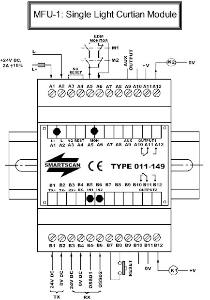
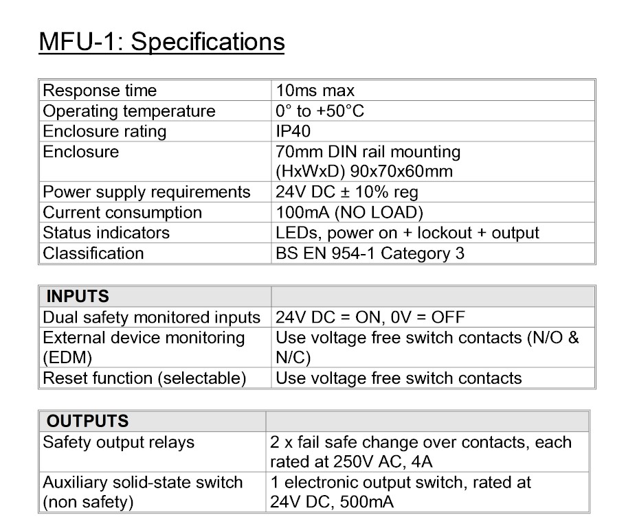
Terminals A1 and A2 – Power supply input - Connect a suitably stabilized 24V DC power supply to terminals A1 = +24V DC and A2 = 0V DC. The current consumption of the MFU with no load applied
on the output switching terminals is 100mA.
Terminal A3 and A4 – Automatic reset mode - Link terminal A3 to terminal A4 if automatic reset is required. In the automatic reset mode no connections are required at terminal B7 and terminal B8.
Terminals A5 and A6 – External device monitor (EDM) - Auxiliary change over contacts, from an external power-switching device are connected across terminals A5 and A6. The monitoring circuit checks that the power switching devices both de-energize at the same time the MFU safety output switches de-energize. If one of the power switching devices fail to de-energize at this time the MFU will trip. If the EDM circuit is not used it is necessary to link terminals A5 to A6 otherwise the system will default into a lockout condition.
Terminals A7 and A8 – no connections Terminals A7 and A8 – no connections
Terminal A9 – Auxiliary electronic switching output - The Auxiliary switching output should only
be used for non-safety critical applications. For example connecting an indicator lamp or as feedback to a PLC to the safety outputs have de-energized.
The auxiliary output, derived from safety input OSSD2, energizes when output switches 1 and 2 energize. Auxiliary output ON = 24V DC and OFF = 0V DC.
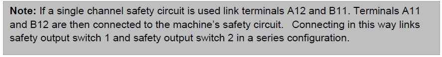
Terminal A10, A11 and A12 – Safety output 1 switch contacts - Terminals A10, A11 and A12 are the output connections to safety relay 1 changeover switching contacts. Terminal A11 is the common output, with terminal A12 as the normally open switch and A10 as the normally closed switch. Normally, terminals A11 and A12 would be connected to one channel of a machine’s stop circuitry. For example, via an external power-switching relay or directly to a safe PLC input or a machines final control element.
Power - Red LED ON when power is ON
Inputs - Green LED ON when input is ON
EDM - Yellow LED ON when EDM is ACTIVE
Wiring Information
Terminals A1 and A2 – Power supply input - Connect a suitably stabilized 24V DC power supply to terminals A1 = +24V DC and A2 = 0V DC. The current consumption of the MFU with no load applied
on the output switching terminals is 100mA.
Terminal A3 and A4 – Automatic reset mode - Link terminal A3 to terminal A4 if automatic reset is required. In the automatic reset mode no connections are required at terminal B7 and terminal B8.
Terminals A5 and A6 – External device monitor (EDM) - Auxiliary change over contacts, from an external power-switching device are connected across terminals A5 and A6. The monitoring circuit checks that the power switching devices both de-energize at the same time the MFU safety output switches de-energize. If one of the power switching devices fail to de-energize at this time the MFU will trip. If the EDM circuit is not used it is necessary to link terminals A5 to A6 otherwise the system will default into a lockout condition.
Terminals A7 and A8 – no connections Terminals A7 and A8 – no connections
Terminal A9 – Auxiliary electronic switching output - The Auxiliary switching output should only
be used for non-safety critical applications. For example connecting an indicator lamp or as feedback to a PLC to the safety outputs have de-energized.
The auxiliary output, derived from safety input OSSD2, energizes when output switches 1 and 2 energize. Auxiliary output ON = 24V DC and OFF = 0V DC.
Terminal A10, A11 and A12 – Safety output 1 switch contacts - Terminals A10, A11 and A12 are the output connections to safety relay 1 changeover switching contacts. Terminal A11 is the common output, with terminal A12 as the normally open switch and A10 as the normally closed switch. Normally, terminals A11 and A12 would be connected to one channel of a machine’s stop circuitry. For example, via an external power-switching relay or directly to a safe PLC input or a machines final control element.
Terminals B1 – 24V DC supply: + 24V DC output for connecting to the light curtain TX.
Terminals B2 – 0V DC supply: 0V DC output for connecting to the light curtain TX.
Terminals B3 – 24V DC supply: + 24V DC output for connecting to the light curtain RX.
Terminals B4 – 0V DC supply: 0V DC output for connecting to the light curtain RX.
Terminal B5 and B6 – light curtain inputs (OSSD1 and OSSD2) -Connect the electronic output switches (OSSD1 and OSSD2) of a 1000 Series light curtain to terminals B5 and B6 respectively.
Terminals B7 and B8 – Reset - If the MFU is required to be in the latch mode a suitable switch
should be connected between terminal B7and terminal B8. If the safety output relays de-energize a depression of the switch is required to re-energize the output switches to an ON condition.
The MFU’s safety output switches will only re-energize when the reset switch is depressed and then released.
If the MFU is required to operate in an automatic reset condition do not connect a switch to terminals B7 and B8. However, it is necessary to link terminal A3 to terminal A4 before an automatic reset condition can be established.
Terminals B9 – No connections
Terminal B10, B11 and B12 : Safety output 2 switch contacts - Terminals B10, B11 and B12 are the output connections to safety relay 2 changeover switching contacts. Terminal B11 is the common output, with terminal B12 as the normally open switch and B10 as the normally closed switch. Normally, terminals B11 and B12 would be connected to one channel of a machine’s stop circuitry. For example, via an external power switching relay or, directly to a safe PLC input or to a machines final control element. Connect terminals A5 and A6 to one channel of a machine’s stop circuitry. For example, via an external power-switching relay or, directly to a safe PLC input or a machines final control element.