
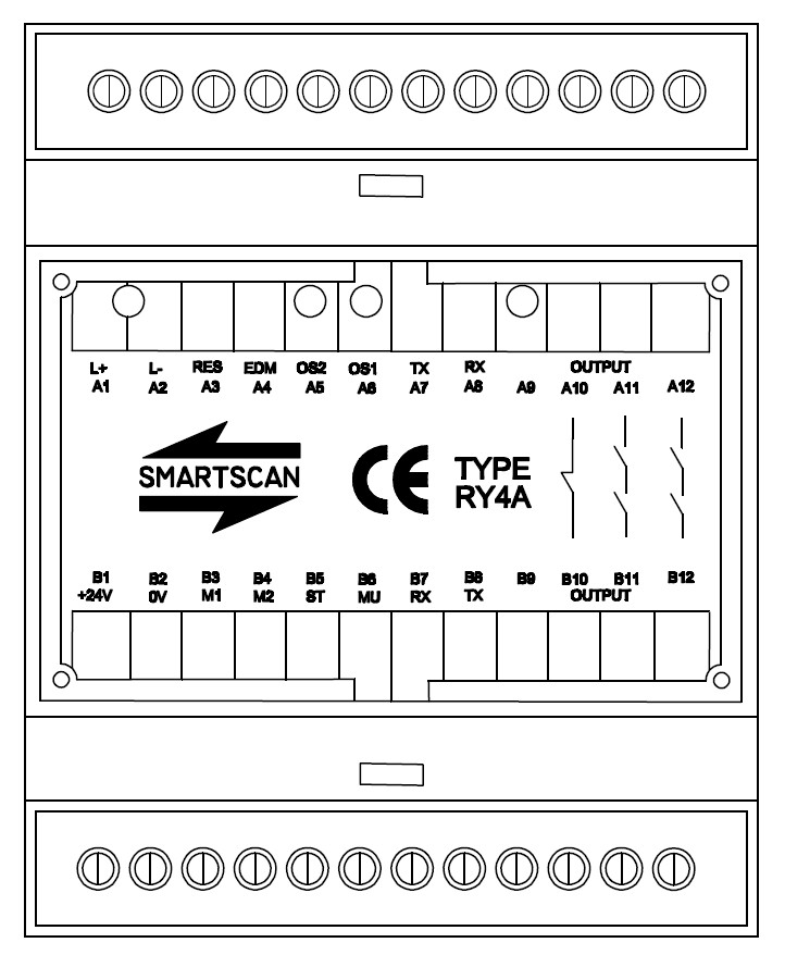
Smartscan Safety Light Curtain: RY4A Module - Single Light Curtain
Status Indicators
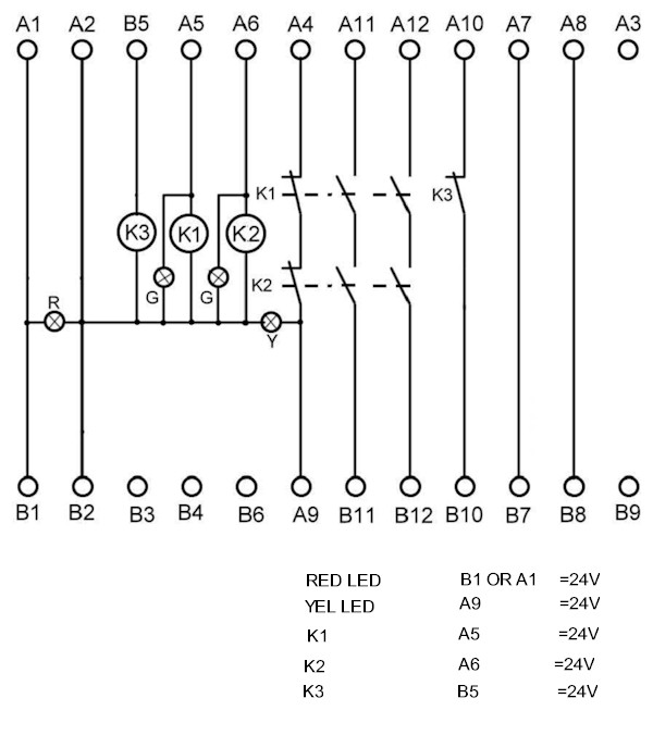
Power - Red LED ON when power is ON
Inputs - Green LED ON when input is ON
EDM - Yellow LED ON when EDM is ACTIVE
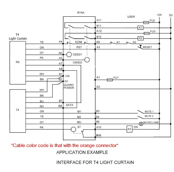
Wiring Information
Terminals A1 and A2 – Power supply input
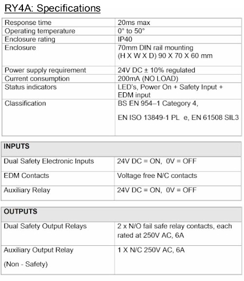
Connect a suitably stabilized 24V DC power supply to terminals A1 = +24V DC and A2 = 0V DC. The current consumption of the RY4A with no load applied on the output switching terminals is 200mA.
Terminal A3
Not internally connected to the box. It provides a junction point for terminating the user reset station to the light curtain reset. If the light curtain and RY4A relay are to be configured in "Automatic Reset" mode connect a 24V DC supply to this terminal instead of through a normally open contact reset switch.
Terminals A4 and A9 – External device monitor(EDM)
Terminal A4 is an EDM input from the light curtain to the RY4A relay.
Terminal A4 is internally connected via N/C contacts of the internal relays to Terminal A9.
EDM is monitors auxiliary normally closed, force guide contacts primarily used for monitoring an external device (if required). E.g. contactors, safety relays (FSD) final switching device etc. There is a yellow LED associated with the EDM monitor that indicates the status of this circuit. may be used as an indicator for fault finding. LED ON = EDM Active.
Terminals A5 and A6 – Safety Inputs
Relay coil inputs to be connected to the device which will energize the internal force guided relays by applying 24V DC. A5 (Receiver Pink wire) and A6 (Receiver Grey wire) may be used for a light curtain input (OSSD1 and OSSD2) e.g. T4 series safety light curtain.
Terminal A7 and B7
Are internally connected contacts and may be used as link terminals. When using the T4 Series light curtain A7 is used to connect the data link from the Receiver head, transmit signal . B7 is used to connect the data link from the Transmitter head, receive signal.
Terminal A8 and B8
Are internally connected contacts and may be used as link terminals. When using the T4 Series light curtain A8 is used to connect the data link from the Receiver head, transmit signal . B8 is used to connect the data link from the Transmitter head, receive signal.
Terminal A10 and A10 – Auxiliary Output
Auxiliary normally-closed relay contact output (non-safety) 250V, 6A.
Terminals A11and B11 – Safety output 1
Connect terminals A11 and B11 to one channel of the machines stop circuitry, for example, via an external power-switching relay, directly to a safe PLC input or a machines final control element. Normally open contact rated 250VAC@6A.
Terminals A12 and B12 – Safety output 2
Connect terminals A11 and B11 to one channel of the machines stop circuitry, for example, via an external power-switching relay, directly to a safe PLC input or a machines final control element. Normally open contact rated 250VAC@6A.
Power - Red LED ON when power is ON
Inputs - Green LED ON when input is ON
EDM - Yellow LED ON when EDM is ACTIVE
Wiring Information
Terminals A1 and A2 – Power supply input
Connect a suitably stabilized 24V DC power supply to terminals A1 = +24V DC and A2 = 0V DC. The current consumption of the RY4A with no load applied on the output switching terminals is 200mA.
Terminal A3
Not internally connected to the box. It provides a junction point for terminating the user reset station to the light curtain reset. If the light curtain and RY4A relay are to be configured in "Automatic Reset" mode connect a 24V DC supply to this terminal instead of through a normally open contact reset switch.
Terminals A4 and A9 – External device monitor(EDM)
Terminal A4 is an EDM input from the light curtain to the RY4A relay.
Terminal A4 is internally connected via N/C contacts of the internal relays to Terminal A9.
EDM is monitors auxiliary normally closed, force guide contacts primarily used for monitoring an external device (if required). E.g. contactors, safety relays (FSD) final switching device etc. There is a yellow LED associated with the EDM monitor that indicates the status of this circuit. may be used as an indicator for fault finding. LED ON = EDM Active.
Terminals A5 and A6 – Safety Inputs
Relay coil inputs to be connected to the device which will energize the internal force guided relays by applying 24V DC. A5 (Receiver Pink wire) and A6 (Receiver Grey wire) may be used for a light curtain input (OSSD1 and OSSD2) e.g. T4 series safety light curtain.
Terminal A7 and B7
Are internally connected contacts and may be used as link terminals. When using the T4 Series light curtain A7 is used to connect the data link from the Receiver head, transmit signal . B7 is used to connect the data link from the Transmitter head, receive signal.
Terminal A8 and B8
Are internally connected contacts and may be used as link terminals. When using the T4 Series light curtain A8 is used to connect the data link from the Receiver head, transmit signal . B8 is used to connect the data link from the Transmitter head, receive signal.
Terminal A10 and A10 – Auxiliary Output
Auxiliary normally-closed relay contact output (non-safety) 250V, 6A.
Terminals A11and B11 – Safety output 1
Connect terminals A11 and B11 to one channel of the machines stop circuitry, for example, via an external power-switching relay, directly to a safe PLC input or a machines final control element. Normally open contact rated 250VAC@6A.
Terminals A12 and B12 – Safety output 2
Connect terminals A11 and B11 to one channel of the machines stop circuitry, for example, via an external power-switching relay, directly to a safe PLC input or a machines final control element. Normally open contact rated 250VAC@6A.

Terminals B1 – 24V DC supply - + 24V DC supply
Terminals B2 – 0V DC supply - 0V DC supply
Terminal B3 and B4
They are not internally connected. They can be used with the T4 Series light curtain to provide the junction point for Mute 1 and Mute 2 input connections from the light curtain to the user.
Terminals B5 – Auxiliary relay coil
It is internally connected to the auxiliary relay coil input, which will energize the internal status relay (Non safety) by applying 24V DC. When using the T4 Series light curtain the status output from the light curtain is connected to this terminal to drive the auxiliary relay.
Terminals B6
It is not internally connected. When using the T4 Series light curtain it is used as a junction point to provide the connection for the mute output signal to the user.
Terminal B9
It is not internally connected. This connection may be used as a junction point for shield / earth connection for the light curtain.