Smartscan Safety Light Curtain T4B: Controls Information
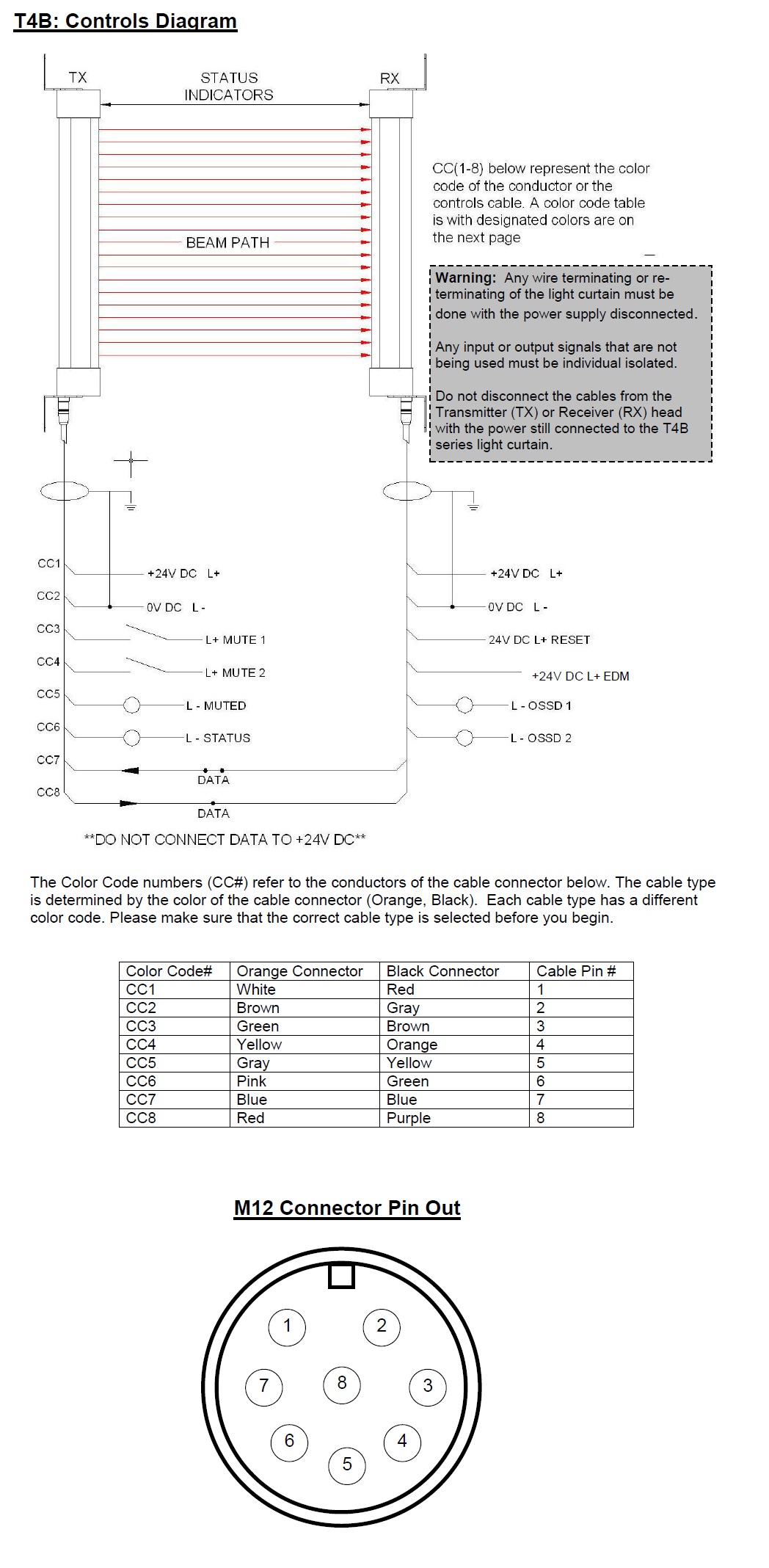
Power supply - Use a regulated supply +24V DC ±10%. Protect the +24V input with a 0.5A fuse. Connect the power supply to both the transmitter (TX) and receiver (RX) cables as follows: Connect conductors CC1 to +24V DC and CC2 to 0V DC.

EDM (External Device Monitoring) - This input is used to monitor external switching devices to ensure those devices respond each and every time the light curtain is interrupted. There is and LED indicator located in the receiver (RX) column that illuminates when the EDM circuit is complete.
All Modes (Manual, Automatic & Restart Interlock): When monitoring a switching device one side of the
Normally Closed circuit will connect to conductor CC4 of the receiver (RX) cable the other side to +24V DC.
All Modes (Manual, Automatic & Restart Interlock): When monitoring a switching device one side of the
Normally Closed circuit will connect to conductor CC4 of the receiver (RX) cable the other side to +24V DC.

Reset - A push button or key switch is required to give the system a manual restart signal. Apply +24Vdc to conductor CC3 of the receiver(RX)cable, releasing the switch will restart the safety outputs to an ON condition, providing the light curtain is clear of obstruction. If using a PLC to pulse the reset signal the pulse width should be 100ms or greater.
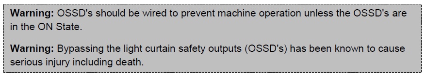
Safety Outputs (OSSD’s) : These two electronic safety outputs respond to interruption of the light curtain (unless muted or blanked). The safety outputs provide +24Vdc (ON) when the curtain is clear of obstruction and 0Vdc (OFF) when the curtain is blocked. They are monitored 24Vdc@500mA signals additionally there are status LED’s located in the top of the receiver column that illuminate when the safety outputs are in the ON or OFF state.
OSSD1 (Safety Output 1): To complete the safety circuit CC5 of the receiver (RX)cable must be
connected to 0Vdc.
OSSD2 (Safety Output 2): To complete the safety circuit CC6 of the receiver (RX) cable must be
connected to 0Vdc.
Status Output – The status output is an electronic NON-SAFETY output that is ON = +24Vdc when the safety outputs (OSSD’s) are ON and OFF = 0vdc when the safety outputs are OFF. The status contact is a 24Vdc@500mA output and has a status LED located in the transmitter (TX) column that illuminates when the status output is ON.
Status Output: To complete the status output circuit conductor CC6 of the transmitter (TX) cable must be connected to 0Vdc.
Mute Inputs (Mute1, Mute2) - Mute inputs (Mute 1, Mute 2) are mute inputs that should be applied to suitable external mute initiating devices. Both mute inputs (mute1 & mute 2) must switch within 2 seconds of each other or the light curtain will not mute (The time interval known as disparity, can be change via dipswitches in the Learned Mode of the light curtain ) When both inputs are active ON (receive 24Vdc), the light curtain will mute (*full mute or **partial mute), e.g. the guards’ safety outputs (OSSD’s) will not respond to an interruption of the light curtain. The light curtain will remain muted for a maximum time (15 minutes or infinite) that can be selected via dipswitch 3 in the standard mode. Additionally there are mute LED indicators located in the top of the transmitter (TX) column that illuminate when the mute signals are applied. Once either of the mute inputs is deactivated (turned OFF) the system will remain muted for an additional 2 seconds as a default.
*Full Mute: The entire sensing region of the light curtain will mute. (Default)
**Partial Mute: A window (specified number of beams) will mute; the remainder of the light curtain
is active. Selectable via dipswitches in the Learned mode.
Mute1: To apply mute 1 signal conductor CC3 of the transmitter (TX) cable must receive a
+24Vdc signal.
Mute2: To apply mute 2 signal conductor CC4 of the transmitter (TX) cable must receive a
+24Vdc signal.
Mute Output - Some machines require a mute signal to indicate that the light curtain is muted. The mute output is an electronic NON-SAFETY output that is ON =+24Vdc when the light curtain is muted and OFF = 0vdc when the light curtain is not muted. This electronic output is rated 24VDC@500mA and has a status LED located in the transmitter (TX) column that illuminates when the light curtain is muted.
To complete the mute output circuit conductor CC5 of the transmitter (TX) cable must
be connected to 0Vdc.
Communication Link - The communication conductors must be connected properly for the system to work, they relay information between the transmitter and receiver columns.
Connect CC7 of the transmitter(TX) to CC7 of the receiver (RX)
. Connect CC8 of the transmitter (TX) to CC8 of the receiver (RX).

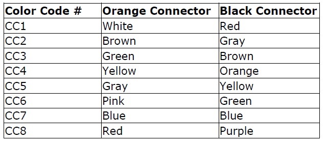
Color Code Table
The Color Code numbers (CC#) refer to the conductors of the cable connector below. The cable type is determined by the color of the cable connector (Orange or Black). Each cable type has a different color code. Please make sure that the correct cable type is selected before you begin.
The Color Code numbers (CC#) refer to the conductors of the cable connector below. The cable type is determined by the color of the cable connector (Orange or Black). Each cable type has a different color code. Please make sure that the correct cable type is selected before you begin.